Pipeline Planning for Trailer Concrete Pumps: Length, Bends and Lift
A trailer pump is only as good as the pipeline it feeds. Length, bend count, vertical lift and mix decide whether a given model achieves its rated output.
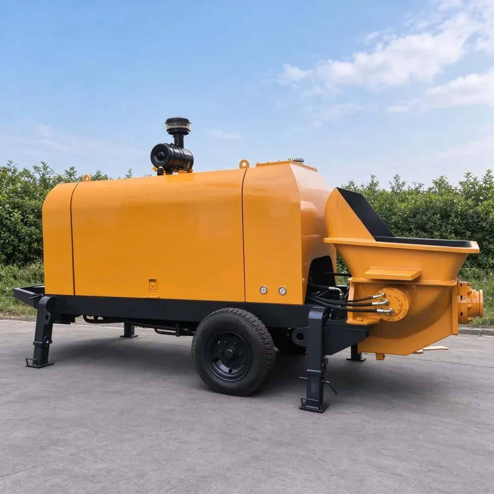
Pipeline length, bend count, vertical lift and mix specification decide what a trailer concrete pump can actually deliver, and they matter more than the model number. A machine that achieves a good rate on a straight 60 m run can struggle on the same distance with six elbows and a 20 m lift, because friction losses accumulate in a way that a headline output figure never shows.
This guide is for contractors planning a pump position and pipeline route, and for dealers who have to answer the question of which model a pour actually needs. It sets out the four route variables, why bends cost more than length, and how to send a route so the answer comes back as a working installation rather than a machine price. It does not cover boom-mounted pumps, which place concrete by boom rather than by pipeline.
Why bends cost more than straight length
Each bend in a pipeline adds localised resistance that a straight length does not. Four elbows over a short run can cost more pressure than an extra thirty metres of straight pipe, which is why a written description of a route is less useful than a drawing with bend positions marked.
The practical rule is to design the route with the fewest bends that still reaches the pour, and to accept a longer straight run in exchange for removing elbows. Routing along a wall and turning once usually beats weaving between columns to save ten metres of pipe.
Vertical lift adds head pressure
Pumping upward adds head pressure to the line on top of friction losses, and the machine has to be matched to that combined resistance rather than to output alone. This is the variable that separates the larger trailer models from the smaller ones, and it is the reason a 20 m lift at 80 m of run asks a very different question of the machine than a flat run of the same length.
The ZHS trailer range runs from the CPD30 through the CPD40, CPD50, CPD60 and CPD80. The larger models are specified where pipeline length, vertical lift and required delivery rate exceed what the smaller ones can sustain, which in practice means high-rise work and infrastructure pours with long routes from a fixed pump position.
Mix specification is half the answer
Slump, aggregate size and pumpability all affect what a machine can move and how hard it has to work to move it. A mix that pumps easily on a short line can block on a long one, and no amount of machine capacity compensates for a mix that is not pumpable over the route in question.
Send the mix specification with the route rather than after the model is chosen. The two together decide the answer, and a quotation that ignores either one is a quotation for a machine rather than for a working installation.
Sustained pours versus short pours
For a sustained pour, the pump is the fixed point the whole operation is planned around: the truck count, the crew size and the pour window all follow from what the machine can deliver at the end of that route. For a short pour, a mid-range machine that runs comfortably within its capability is usually better value than a large one that spends the day lightly loaded.
The CPD50 sits in the middle of the range and is the model most often specified for sustained commercial pours, where the entry models would run near their limit and the larger units would never use their capacity. That is a value judgement about duty cycle rather than a technical limit.
Where a trailer pump stops being the right tool
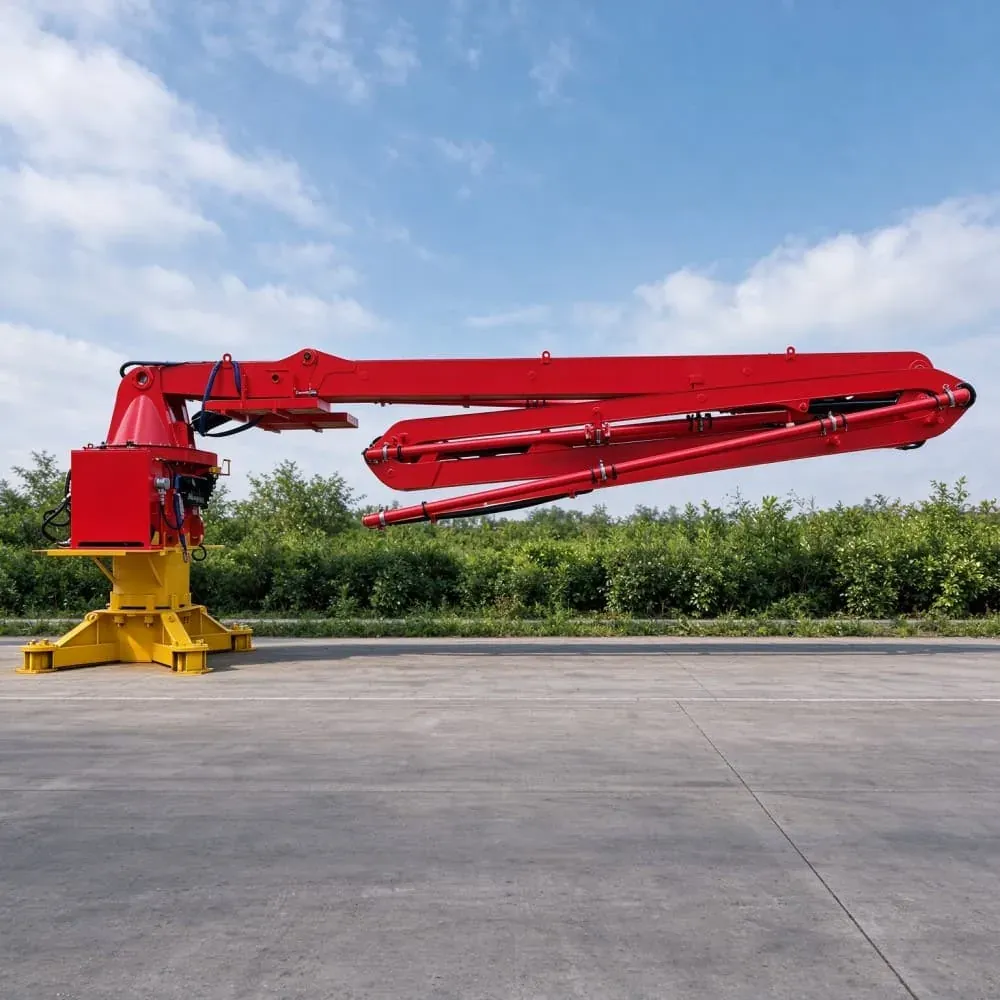
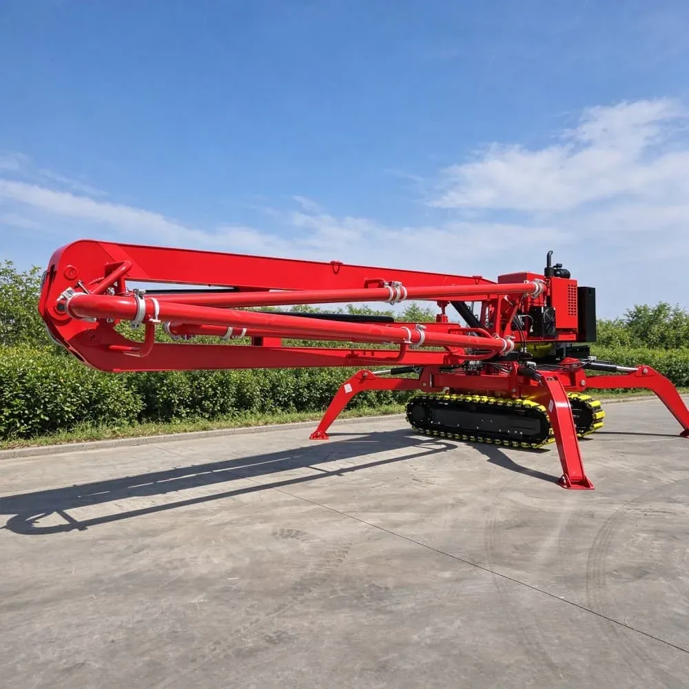
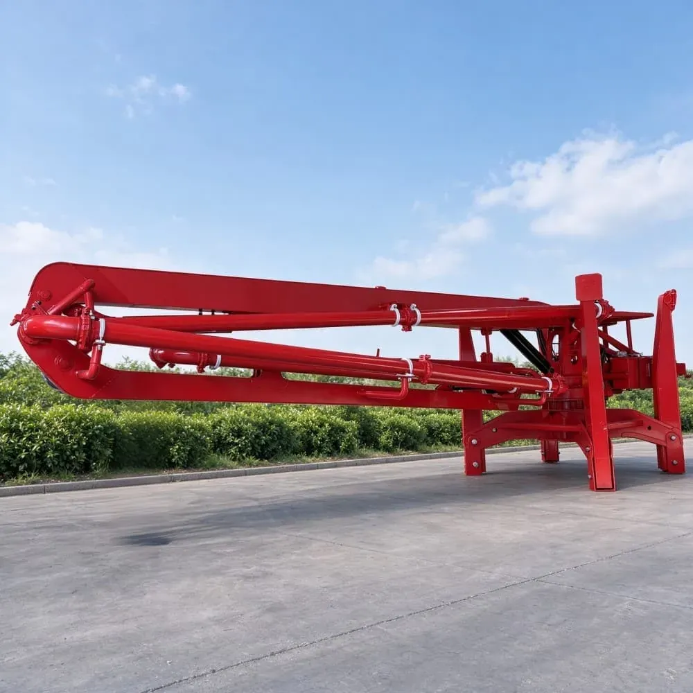
A trailer pump delivers concrete along a pipeline; it does not distribute concrete across formwork on its own. Where the pour has to be spread over a wide area, a placing boom at the end of the line carries the concrete the last part of the way, or a crew works with hoses.
The two formats are complementary rather than competing. On a project that needs both long-distance delivery and reach over formwork, the trailer pump feeds the boom inlet and each machine does what it is good at.
Pipe diameter and wall thickness
Pipe diameter has to be matched to the machine and the mix, not chosen for convenience. A line that is too small raises friction losses and can block on a coarse mix, while a line that is too large for the output can allow the concrete to stall in the pipe between strokes. The larger trailer models also impose more load on every joint, so wall thickness and coupling specification belong in the same decision as the model.
The ZHS placing boom range uses a Φ125 mm delivery pipe with a 3 m end hose, and where a trailer pump feeds a boom inlet the two specifications have to agree. Mixing a pump line and a boom line of different diameters at the junction creates a local restriction that shows up as a pressure spike rather than as a clean transition.
Support and sealing decide whether the route survives
A pipeline that is not supported will sag between joints, and a sagging section holds concrete that then has to be pushed uphill on the next stroke. Support spacing, coupling torque and seal condition all affect whether the route performs as designed, and none of them appear on a machine specification sheet.
Seals are the most common field failure on a long run: a worn coupling leaks slightly, the pressure drops at the far end, and the crew compensates by pushing the pump harder, which accelerates wear everywhere else. Checking couplings at every joint before the pour is cheaper than diagnosing a pressure problem at the tip.
Diagnosing a blockage without guessing
When a line blocks, the position of the blockage tells you what went wrong. A block near the pump usually points to a mix that is too dry or a hopper that ran low. A block at a bend points to a route that put too much localised resistance in one place. A block at the far end often points to a delivery rate that exceeded what the pipe could carry over that distance.
That diagnosis is why the route drawing matters after the pour as well as before it. A crew that knows where the bends are can work backward from the block position, and a crew that only has a verbal description of the route spends the first hour guessing.
Planning the pump position before the route
The pump position and the pipeline route are one decision, not two. A pump placed close to the pour shortens the line but may sit where the concrete trucks cannot reach it; a pump placed for truck access may add forty metres of pipe and two elbows to every pour. On a site with a fixed pump position for weeks, that trade is made once and should be made on a drawing.
The usual compromise is a position with clear truck access on one side and a route into the pour on the other, with the pipe run supported along the route rather than laid across traffic. On a tight urban site, the compromise is often a pump position outside the site boundary with a longer route in, because keeping the access road clear matters more than pipe length.
What a route drawing should show
Draw the route with the pump position, every bend, the vertical sections and the pour point marked, then mark the total length. Add the pipe diameter you intend to run and the number of couplings, because couplings are where pressure is lost and where the line is most likely to fail.
A drawing also makes the route reviewable by the site team before the pour, which is when problems are cheap to fix. A route that crosses a traffic lane or passes through an area that will be backfilled next week is obvious on a drawing and invisible in a written description.
Matching the model to the route, not the other way round
Choosing a model first and then designing a route to suit it inverts the correct order. The route is a set of physical constraints and the model is the thing that has to overcome them, so the route comes first and the model is chosen to suit. That is why we ask for the route rather than for a volume figure.
Cleaning and changeover between pours
Between pours the line has to be cleaned, and how that is done affects the route design. A line with a low point that cannot be drained, or a section that cannot be reached for a sponge, will hold residue that hardens between pours, and a partially blocked line behaves like a longer one on the next stroke.
Send the route, get a working installation
Send the total pipeline length, the bend count with positions marked, the vertical lift, the pipe diameter you intend to run, the mix specification and the required delivery rate. With those six inputs our engineering team confirms which model achieves the rate on your site and what the pipeline needs to look like.
ZHS builds the trailer range to CE and ISO compliance with an 8-hour factory hydraulic and water pumping test on every unit, a 1 year or 2,000 hour guarantee, and ODM production for dealers. Machines can be configured for your market voltage and certification requirements.