How to Choose a Concrete Placing Boom for a High-Rise Floor Plate
Reach, outrigger span, hoisted weight and deck capacity decide which placing boom fits a high-rise floor plate. Here is the order to check them in.
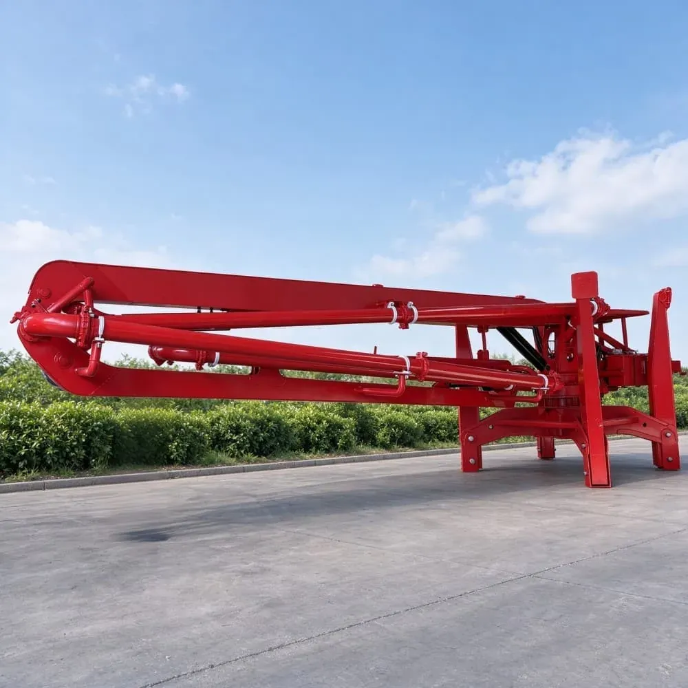
Choose a concrete placing boom by matching four figures to the building: the furthest pour distance from a workable machine position, the outrigger footprint the machine needs, the hoisted weight at the crane hook, and the load the deck can carry at the outrigger points. Reach alone does not decide it, because a 22 m boom that cannot be positioned on the deck is worth less than a 16 m boom that can.
This guide is for contractors and dealers specifying a boom for a mid-rise or high-rise floor plate, where the pump stays at one level and the boom distributes concrete across the slab. It sets out the four checks in the order they eliminate options, then shows how the ZHS spider and self-climbing ranges map onto them. It does not cover ground-level pours, where a trailer pump and pipeline are usually the better answer.
Start with the furthest pour distance, not the floor area
The number that decides the model is the distance from a possible machine position to the furthest point concrete has to reach, not the total floor area. A 1200 square metre floor can be covered from one central position with a 20 m boom, or need three setups from an 11 m machine, and the second case usually costs more in crane time than the larger machine costs to buy.
Measure to the far corner of the actual pour, including any offset for the pump position and the pipe run around columns. On a floor with a central core, the furthest point is often diagonal rather than straight across the plate, which pushes the requirement up by several metres compared with a naive reading of the plan.
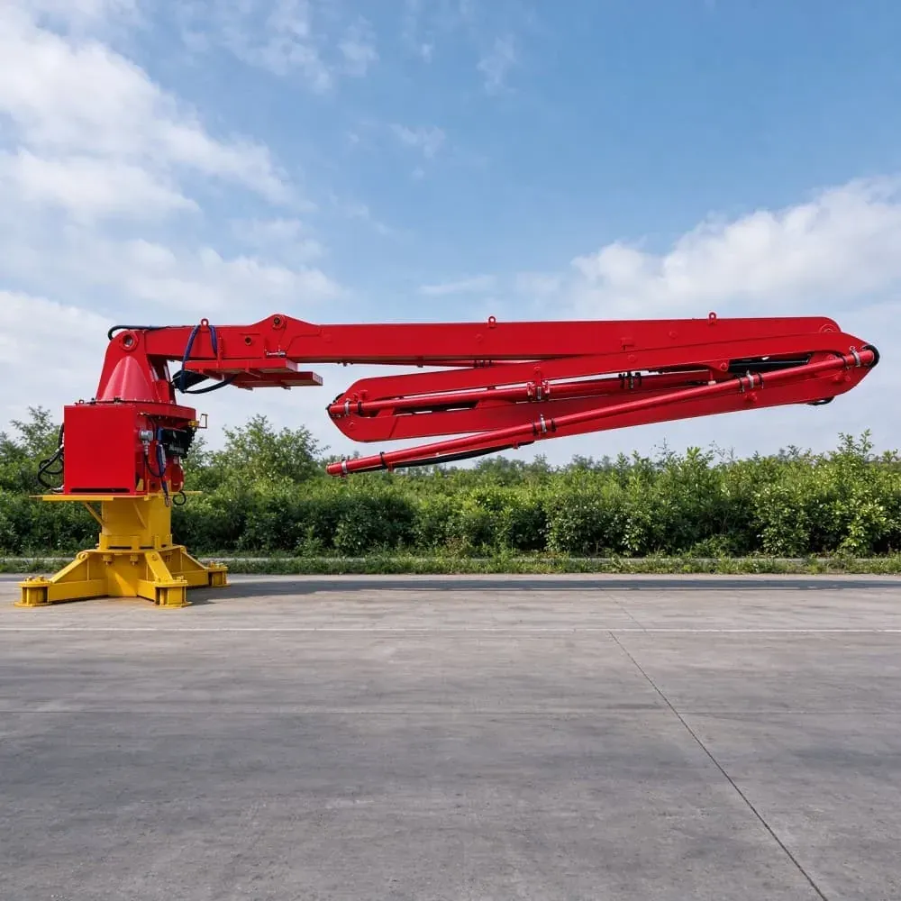
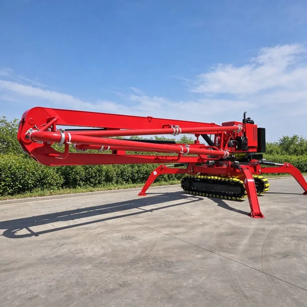
The ZHS spider range spans 11.6 m to 22.5 m of horizontal reach across seven models, with the PB17-3 at 16.5 m covering a typical residential floor plate from one or two positions and the PB23-3 at 22.5 m covering a wide plate that no three-section machine below it touches.
Check the outrigger footprint against the deck
A boom needs a footprint before it needs reach. The PB12-2 opens to 2325 by 2325 mm, the PB17-3 to 4000 by 4000 mm, and the four-section PB21-4 to 5000 by 5000 mm. A five metre footprint is a generous position, and on a deck with a dense column grid it may not exist at all, which rules out the machine regardless of its reach.
Check the footprint against the slab edge, the core walls, the hoist opening and any set-down area. A boom whose outriggers sit over a transfer beam is easier to justify to a structural engineer than one spreading load across a suspended slab mid-span.
The corollary matters for dealers quoting from a range sheet: the largest model in a range is not automatically the safest recommendation. If the deck cannot host the footprint, the honest answer is the smaller machine plus one more setup, and that conversation belongs in the quotation rather than on site.
Weigh the machine both ways
Every ZHS spider boom is quoted with two weights: without counterweight and with it. The PB12-2 runs 1.8 t bare and 2.8 t counterweighted; the PB17-3 runs 3.2 t bare and 5.4 t counterweighted; the PB21-3 runs 4.2 t and 6.2 t; the PB23-3 runs 4.5 t and 6.5 t.
Those two figures change the crane lift plan and the deck load case. A machine at 3.2 t may be liftable with the site crane that is already on the project; the same machine at 5.4 t may need a larger crane booked in advance. Deciding which weight state to plan for is part of the specification, not an afterthought once the machine arrives.
The counterweight exists to keep the boom stable at reach. Running without it reduces hoisted weight and increases the range of positions the crane can serve, at the cost of how far the boom can be worked fully extended.
Check the deck capacity at the outrigger points
Temporary works load is a structural engineering question, and the answer depends on where the outriggers land relative to beams and columns rather than on the machine weight alone. Send the deck plan with the intended position marked and the structural engineer will confirm which load case applies.
This check is where most high-rise boom specifications fail, and it fails late, after the machine is already ordered. Building it into the enquiry saves the situation where a larger boom is delivered to a deck that cannot take it, and the fallback is a smaller machine with more setups than the programme allowed for.
When a self-climbing boom removes the question entirely
If the building is a tower with a continuous core and repetitive floor plates, a self-climbing boom sidesteps the crane lift and the per-floor outrigger deployment altogether. The frame grips the core and climbs with the structure, so the concrete delivery point stays above the working deck and the pump stays in one position for the whole climb.
The ZHS self-climbing range runs from the PB28-3 through the PB32-3, PB33-4, PB36-4 and PB40-5, and the choice between them is driven by floor plate size and the number of frame moves the programme tolerates rather than by a headline reach figure. Because the frame is designed against the core, a self-climbing boom cannot be specified from a range table: the technical sheet is completed for the building.
Self-climbing is the wrong answer where the core stops and starts, where the slab geometry changes drastically between levels, or where the same boom could be shared across two buildings on one development. In those cases a crane-lifted spider boom adapts with far less engineering.
R, Z and M booms do different jobs
Boom folding pattern matters as much as reach when the pour is obstructed. An R boom folds in an arc and works well over an open slab, because the tip can be swung out and dropped without the base being moved. A Z boom folds back on itself, which lets the tip reach over a parapet and then descend into an opening behind it. An M boom adds a fourth articulation point, and the PB21-4 uses four M sections specifically for that extra control on congested sites.
The practical difference shows up the first time the pour point sits behind a column line or inside a shaft. An R boom of the same reach has to be positioned further back and often cannot land the hose where the concrete is needed, while a Z or M boom can fold around the obstruction. That is why the PB14-3 uses three Z sections and the PB21-4 uses four M sections rather than simply extending the R design.
Dealers quoting from reach alone miss this. Two machines with the same horizontal reach can have entirely different usable coverage on a congested floor, and the difference only becomes visible when the boom is deployed on site. Ask what the pour geometry looks like, not just how far it has to reach.
Cable control or radio remote
Both control options appear in the ZHS range: the PB12-2 offers panel or radio remote, the PB17-3 offers cable or radio remote, and the larger three-section machines use switching value or analog remote control. The choice matters on sites where radio interference from other equipment is a known problem, because a cable gives the operator a hard line instead of relying on a wireless link.
Radio remote is faster to set up and lets the operator stand where the pour is visible. Cable control requires a run to the operator position but does not drop out. Contractors working in dense urban sites with several radio systems in use often specify cable after one bad experience with a dropped signal at full extension.
The four-section PB21-4 uses analog quantity remote control with proportional valves, so joystick displacement maps to valve opening rather than to a fixed on or off state. On a congested site with inserts, post-tensioning ducts and starter bars to clear, that resolution is the difference between placing the hose precisely over a formwork gap and overshooting it.
The four figures to send with an enquiry
First, the maximum horizontal distance from a workable machine position to the furthest pour point. Second, the outrigger footprint the site can host. Third, the deck or slab capacity at those outrigger points. Fourth, the pipe run from the pump outlet to the boom inlet, including how many bends it needs.
Add the destination port, the certification your market requires and, for dealers, the annual volume you expect. With those inputs our engineering team replies with the confirmed configuration, the documentation set for your market and a delivery window, and names the model that fits rather than the largest one in the range.